Autocad Professional Course
This AutoCAD Professional Course takes you from 2D sketches to detailed drawings, covering layers, projections, and modifications with practical exercises, empowering architects, engineers, and manufacturers to design accurately and efficiently

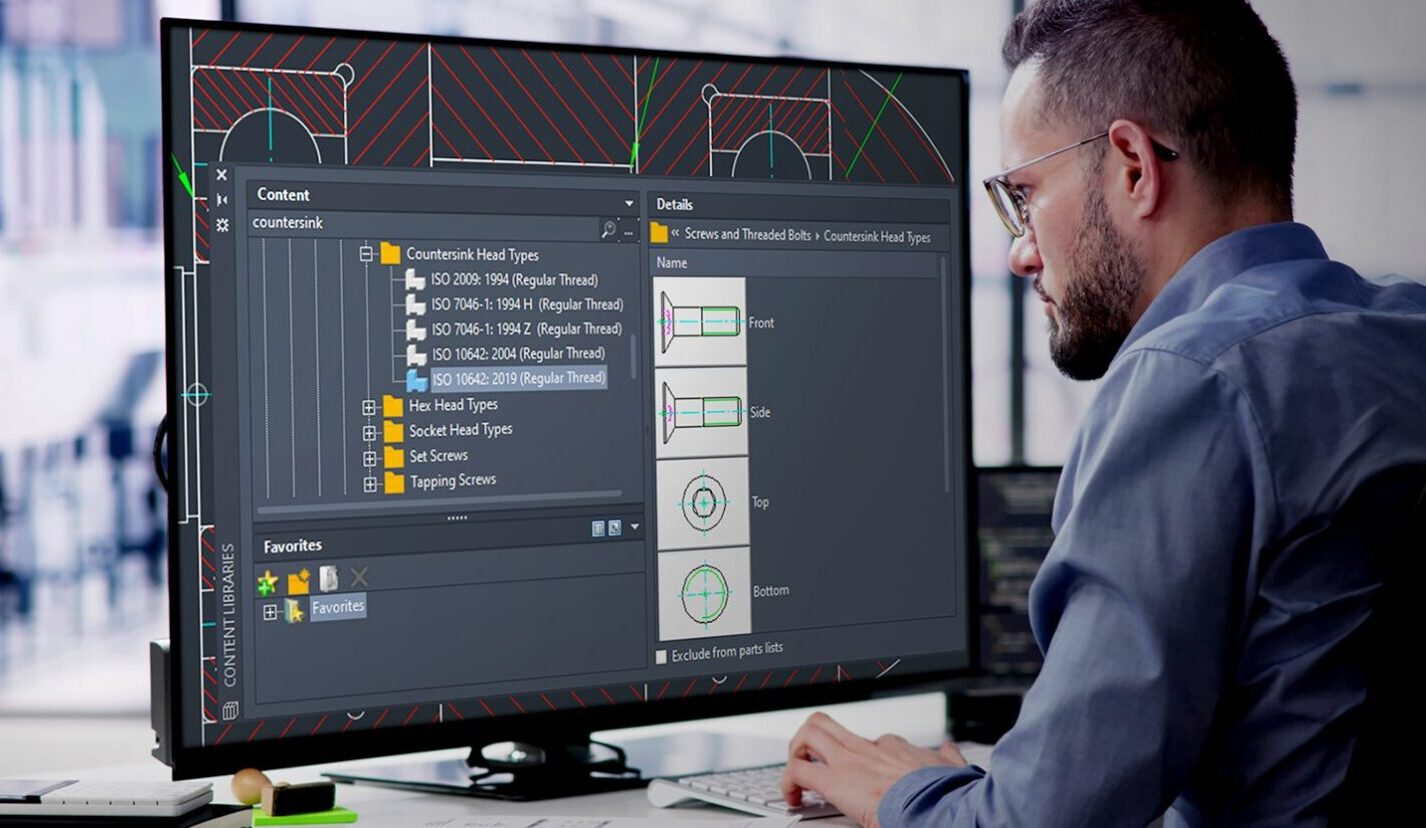
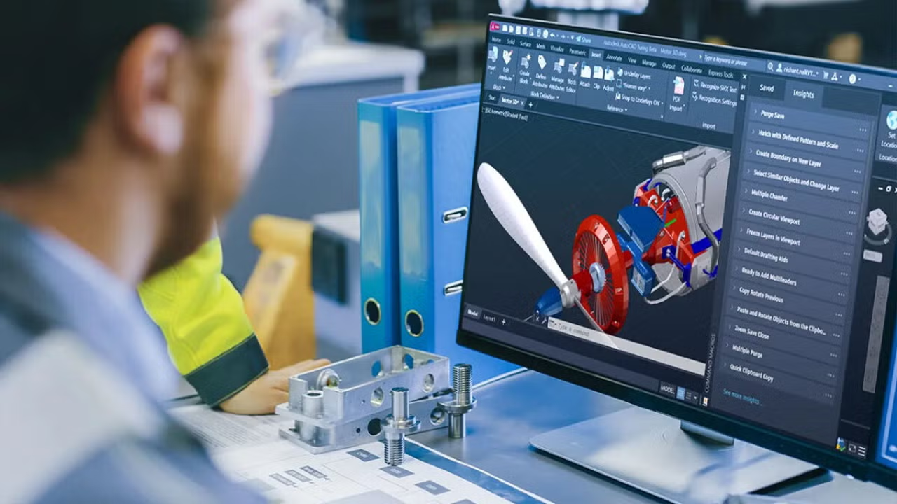
AutoCAD is widely used in industries such as construction, architecture, mechanical engineering, electrical design, interior design, and manufacturing for creating precise 2D drawings and basic 3D models.
Engineers and designers use it for layouts, detailed drafting, shop drawings, plant layouts, and documentation. Companies like AECOM and Larsen & Toubro rely on AutoCAD for accurate design communication and project execution.
This course explains fundamentals and every tool required to create professional drawings, improve productivity, reduce design errors, and support collaboration across teams. It is essential for converting design concepts into technical drawings used in real industrial and construction projects.
The future scope of AutoCAD remains strong due to continuous demand in infrastructure, smart cities, industrial plants, and digital construction projects. Skilled professionals are required for roles such as CAD drafter, design engineer, and BIM technician.
Companies such as Autodesk and Wipro support digital design transformation, increasing demand for CAD expertise. Integration with BIM, cloud collaboration, and automation tools is expanding career opportunities.
This course provides strong fundamentals and tool-based knowledge, enabling professionals to work in global engineering, architecture, and manufacturing industries, ensuring steady career growth and long-term employability in evolving design environments.
Course Syllabus
It provides an overview of what you are going to learn.
- Things to consider in Design
- Product Lifecycle management
- Orthographic projection
- Intro about AutoCAD
- How to set units
- How to set Limits
- Function Keys
- Objectives
- Absolute coordinate system
- Relative coordinate system
- Relative - polar coordinate system
- Line in profile
- Circle in profile
- Arc in profile
- Ellipse in profile
- Rectangular in profile
- Objectives
- Polygon in profile
- Polyline in profile
- Polyline Edit
- Spline in profile
- Spline Edit
- Objectives
- Point in profile
- Multiline profile
- Multiline Edit
- Region in profile
- Donut
- Move Entity
- Copy Entity
- Stretch & Rotate
- Mirror Entity
- Scale Entity
- Objectives
- Trim Entity
- Extend Entity
- Chamfer Entity
- Fillet Entity
- Array – Rectangle
- Array – polar
- Array – Path
- Example & Practice Drawing
- Objectives
- Hatch Entity
- Boundary Entity
- Join Entity
- Explode Entity
- Break & Break at point
- Example & Practice Drawing
- Objectives
- Offset Entity
- Lengthen
- Copy clip & Paste clip
- Zoom Entity
- Dimension Tools
- Dimension Radius
- Dimension Associate
- Jogged & Jog line Dimension
- Dimension Edit
- Dimension Style
- Center mark & Center line
- Geometrical constrain
- Dimensional Constrain
- Measuring Geometry – Area
- Measuring Geometry
- Text & Annotations
- Text Style
- Text Edit
- Text Align
- M Text & Annotations
- Block Annotation
- Block Edit – point
- Block Edit – Linear
- Block Edit – Polar
- Block Edit – Rotate
- Objectives
- Block Edit – Scale
- Block Edit – Flip
- Block Edit – Array
- Block Edit - BV State
- WBlock Annotation
- Attribute
- Attribute Multiline
- Enhanced Attribute Edit
- Block Attribute Manager
- Attribute Edit – GATTE
- Attribute Edit – Pedit
- Group
- Q Leader
- MultiLeader
- MultiLeader Style
- MultiLeader Edit
- MultiLeader Collect
- MultiLeader Align
- Layer & its properties
- Layer Turn off & Freeze
- Layer Lock
- Layers - Match properties & Match Layer
- Layer plot
- Objectives
- Detail about specific icons in Layers
- Layer - VP Freeze
- Difference of BY Layer & BY Block
- Properties
- Quick properties
- Tables annotations
- Layout Setups
- Design center
- X Line Feature
- Ray Line Feature
- Export Feature
- Image Feature
- Import Feature
- Navigation Bar
- Options Feature
- Purge Feature
- X Ref Feature
- About Isometric
- Example 01 - solid edges
- Example 02 - solid + cylindrical edges
- Example 03 - Sectioned Part
- How to add dimension in isometric
Enrollment Process
choose the access type you prefer to learn
Get a free e-book for lifetime access

The Ultimate interview guide
Aerospace, Automotive, Healthcare, Energy, HVAC, Manufacturing & Tooling, Metallurgical, Oil, gas & petroleum

Top Interview Questions & Answers
Material Science and Engineering, Manufacturing & Production,Thermodynamics & Heat transfer, Mechanical Design, Quantitative Aptitude
Frequently asked questions
Here are some common questions about our company.
The primary purpose of AutoCAD is to explain the geometries in blueprints. This 2D drawing explains every part of the model in mechanical, civil, and electrical in orthographic projections, mostly by utilising commands to build the profiles.
Before learning modelling, we need to understand what 2D and 3D drawings are.
Why should we use that, and what is the objective of sketch profiles?
How to Use Modifying Entities and Create a Proper Blueprint
All of that is mostly used to easily convey the drawing to manufacturing prior to entering any sector.
Yes absolutely, because
AutoCAD is widely used across industries like architecture, engineering, construction, manufacturing, and more. It's the go-to software for creating precise 2D and 3D designs.
Having AutoCAD skills can open doors to a wide range of job roles with competitive salaries. You can work as a drafter, designer, project manager, or even start your own business.
As technology continues to evolve, AutoCAD remains relevant. Learning AutoCAD ensures you stay ahead of the curve and adapt to industry trends
Yes, you can learn with no design experience
You will quickly learn how to use each tool and where to place it after learning how to use it with an example.
If you don't have enough cash to buy our course, you can pay in two installments.