Solidworks Professional Course.
This comprehensive Solidworks course builds expertise in modeling, assemblies, sheet metal, weldments, and drafting equipping students and professionals to transform ideas into precise, efficient, and innovative product design
Enquiry form !
Our team will reach you in 24 hours
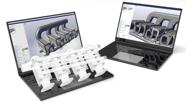
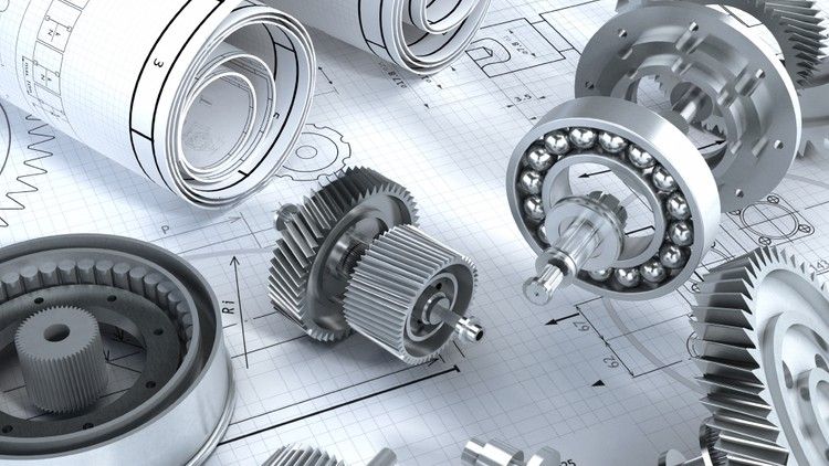
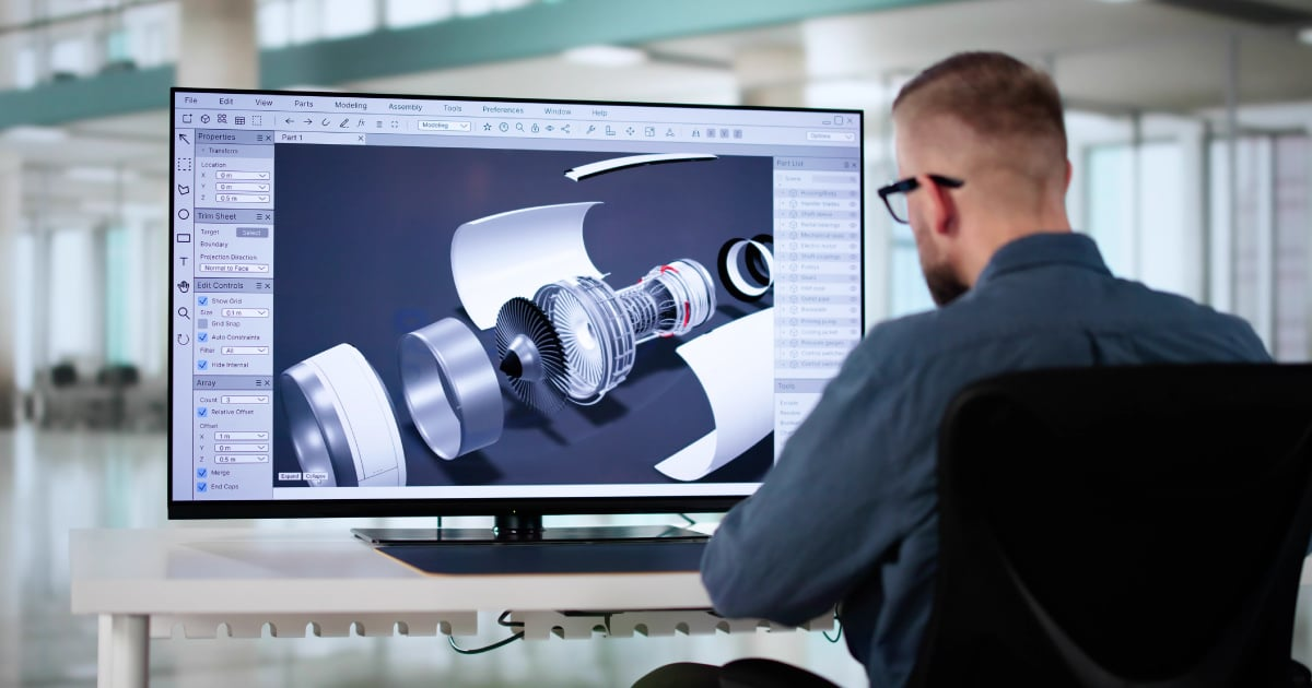
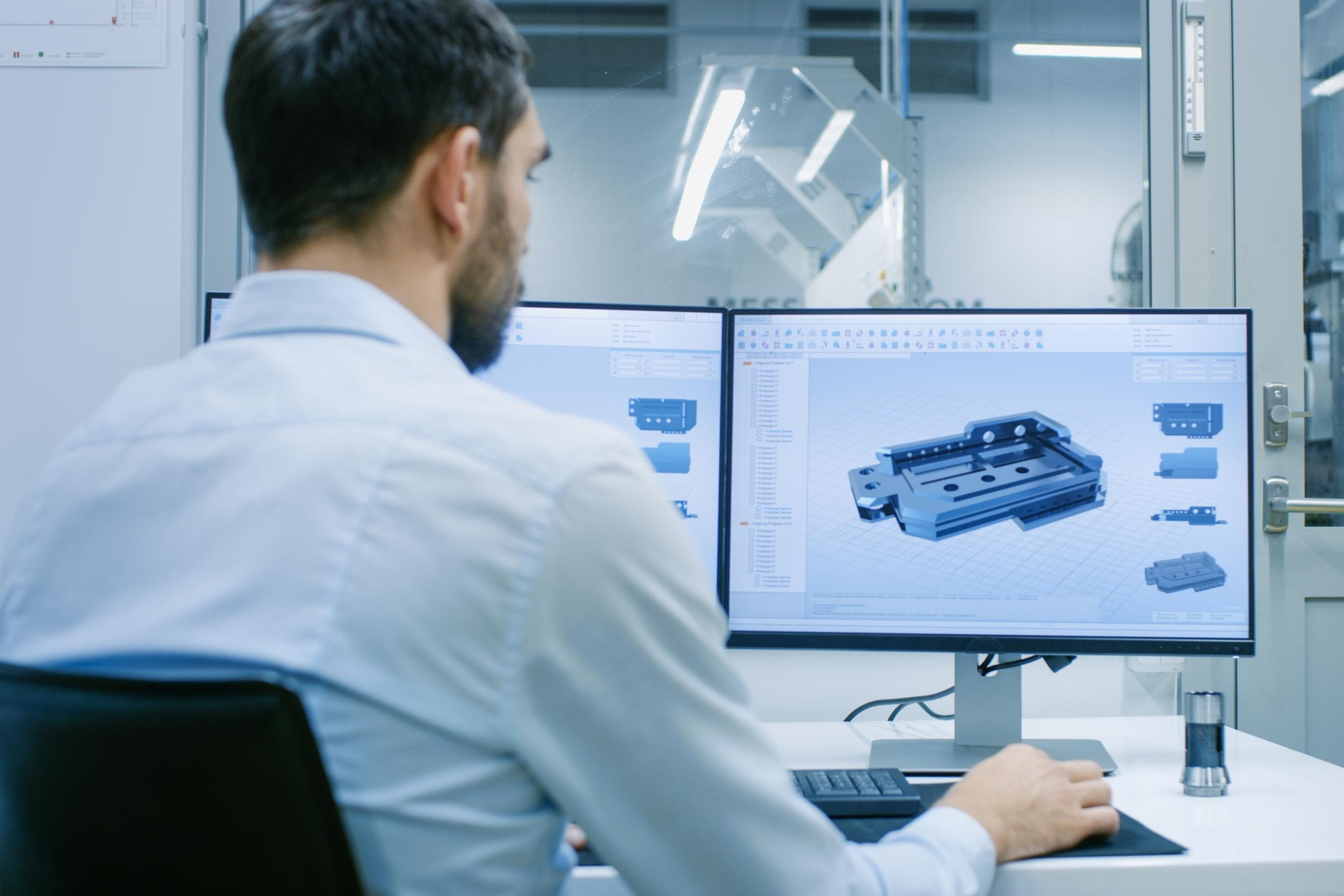
Engineers use solid modeling to create accurate industrial parts like gears, shafts, housings, sheet metal components, and assemblies, enabling virtual testing, simulation, and validation before production.
It helps reduce product development time, minimize design errors, improve product quality, and support advanced manufacturing methods such as CNC machining, 3D printing, and automation.
Surface modeling is widely used in industries such as automotive, consumer electronics, aerospace, medical devices, and industrial product design, where aesthetics, ergonomics, and functional appearance are critical.
Designers create complex freeform surfaces for car exteriors, interior trims, dashboards, lighting components, and high-quality consumer products. Companies like Tata Motors and Hyundai Motor Company use advanced surface modeling to develop attractive, aerodynamic, and manufacturable designs.
Sheet metal and weldment design are widely used in industries such as automotive, heavy machinery, construction, electrical enclosures, HVAC, and industrial equipment manufacturing.
Engineers design components like brackets, cabinets, chassis, frames, and structural assemblies using precise modeling and fabrication standards. Companies such as Larsen & Toubro and Ashok Leyland use these skills for strong, lightweight, and cost-effective structures.
The future scope of solid modeling is very high due to the growth of digital manufacturing, smart factories, Industry 4.0, and product innovation across sectors.
This course provides a strong foundation in fundamentals and all design tools, enabling professionals to work in global industries, startups, and innovation-driven companies. Continuous advancements in automation and customization will further expand career opportunities and long-term growth in industrial component design.

The future scope of surface modeling and automotive styling is very promising due to growing demand for innovative product appearance, electric vehicles, and user-focused design.
Companies such as Tesla, Inc. and Mahindra & Mahindra require skilled surface designers to develop modern and sustainable vehicle designs.
Opportunities include automotive surface designer, product stylist, digital sculptor, and transportation designer.
The future scope of sheet metal and weldment design is very high due to increasing demand in infrastructure, electric vehicles, renewable energy, and automation industries.
Skilled professionals are required for roles such as design engineer, fabrication engineer, and structural product designer. Companies like Siemens and ABB need designers for industrial machinery, robotics, and energy systems.
Growth in smart factories, modular construction, lightweight materials, and robotic welding is expanding opportunities.
Course Syllabus
It provides an overview of what you are going to learn.
- Things to consider in design
- Product Lifecycle Management
- Intro about solidworks
- How to set units
- Views Tab
- Sketch Profiles
- Trim Entities
- Convert Entities
- Offset Entities
- Mirror & Pattern Entities
- Extruded Bose
- Extruded cut
- Revolved Bose
- Revolved cut
- Swept Bose Feature
- swept cut feature
- Reference geometry planes
- Formation of plane using vertex
- Tangency plane
- Lofted Bose feature
- Lofted cut
- Boundary bose Feature
- Boundary cut feature
- Hole wizard
- Theard feature
- Fillet feature
- Chamfer feature
- Linear pattern
- Circular pattern
- Curve driven pattern
- Fill pattern
- Table driven pattern
- Sketch driven pattern
- Variable pattern
- Shell Feature
- Draft Feature
- Wrap feature
- Intersect feature
- Mirror feature
- Combine feature
- Dome feature
- Indent feature
- Flex feature
- Scale feature
- Split feature
- Helix & spiral curve
- Helix & spiral curve - section 02
- Helix & spiral curve - section 03
- Helix & spiral curve - section 04
- Curves through XYZ point
- Curves through reference point
- Split line
- Split line - other types
- Extruded Surface
- Extruded Surface – Draft
- Revolved surface
- Objectives
- Swept surface
- Swept surface with guide curves
- Lofted surface
- Objectives
- Boundary surface
- Boundary surface in aerofoil shape
- Filled surface
- Planar surface
- Objectives
- Offset surface
- Ruled surface
- Ruled surface - Taper & perpendicular to vector
- Ruled surface – Sweep
- Delete face – Delete
- Delete face - Delete & patch
- Delete face - Delete & fill
- Objectives
- Replace face
- Delete hole
- Extend face
- Trim surface
- Trim surface types
- untrim surface
- untrim surface detail
- Objectives
- Knit surface
- Thicken
- Cut with surface
- 3D Curves - Composite & Project cuves
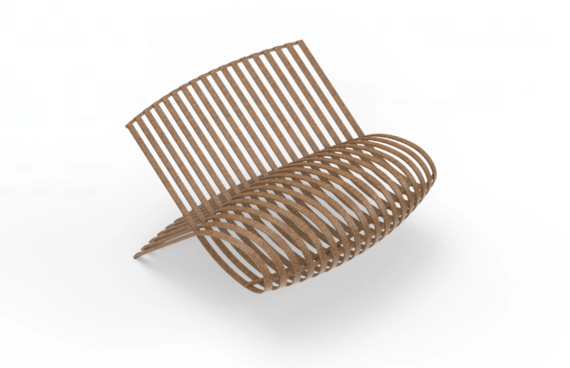
- Rocking wheel chair
- Patterned Water Bottle
- Wooden chair
- Egg shaped mouse
- what is sheetmetal
- Types of cutting machine
- Types of bending machine
- Types of steel sheet
- Sheetmetal from design to maufacturing
- Difference of K-Factor, Bend allowance & Bend deduction
- Practical relation of sheet metal
- Base Flange
- Edge Flange
- Miter Flange
- Brief of Hem
- Brief of Jog
- Sketched Bend
- Cross Break
- Swept Flange
- Corner: Break Corner
- Corner Relief
- Welded corner
- Closed Corner
- Forming tool
- Sheetmetal Gusset
- Extruded cut & simple hole
- Brief of Vent
- Lofted Bend
- Convert to sheet metal option
- About Fold & unfold option
- Flange wall
- T Flex Flange
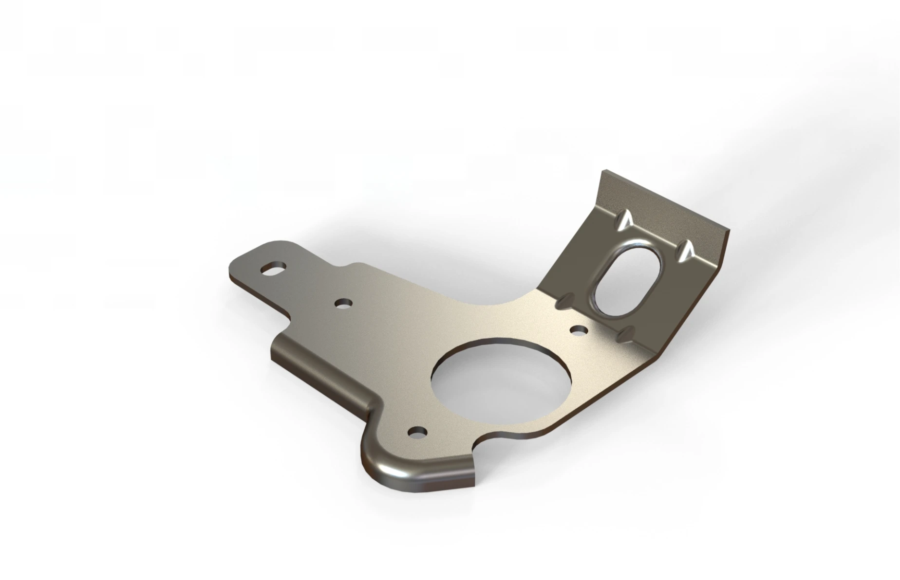
- Bracket
- Sheetmetal Cabinet Design
- DC power supply Enclosure
- metal Enclosure
- What is Weldment
- Different techniques for creating weldments
- Extraction of weldment external model
- Structural member: Locate profiles
- Trim Extend
- End Cap
- Weldment Gusset
- Weld Bead
- Taffic cone
- Air terminal support
- Table frame
- Top Frame
- Base Holding sturcture
- Angular supporting structure
- Ladder structure
- Top Frame safety structure
- Bottom supporting frames
- Full structure Assembly
- About Assembly
- Assembly in solidworks
- Objectives
- Standard mate: coincident
- Standard mate: parallel
- Standard mate: perpendicular
- Standard mate: concentric
- Standard mate: Fix mate
- Standard mate: Distance
- Standard mate: Tangency
- Standard mate: Angle mate
- Objectives
- Advance mate: Profile center
- Advance mate: Symmetric
- Advance mate: Width
- Advance mate: Linear mate
- Advance mate: Distance limit
- Advance mate: Angular limit
- Advance mate: path mate
- Objectives
- Mechanical mate: Cam
- Mechanical mate: Slot
- Mechanical mate: Screw
- Mechanical mate: Hinge
- Hinge mate in detail
- Mechanical mate: Gear
- Mechanical mate: Universal joint
- Universal joint in detail
- Mechanical mate: Rack & pinion
- Objectives
- Additional feature: Duplicate parts
- Additional feature: form sub assembly
- Assembly Modelling
- Additional feature: Open part
- Additional feature: Isolate
- Additional feature: Exploded view
- Objectives
- Additional feature: Bill of material
- Additional feature: Driven component pattern
- Additional feature: Linear component pattern
- Additional feature: Sketch Driven pattern
- Additional feature: Move & Rotate component
- Objectives
- Additional feature: Standard part
- Additional feature: Smart fastners
- Additional feature: Copy with mate
- Additional feature: Edit component
- Additional feature: Add material
- Additional feature: Top Down assembly
- Additional feature: New Part
- Objectives
- Evaluate: Interference Detection
- Evaluate: Clearance verification
- Evaluate: Hole alignment
- Evaluate: Assembly visualisation
- Evaluate: Assembly visualisation – 02
- Evaluate: Performance
- Objectives
- Evaluate: Mass properties
- Evaluate: Measure
- Evaluate: Section properties
- Evaluate: Body compare
- Objectives
- Evaluate: Curvature
- Evaluate: Sustainability
- Evaluate: Costing
- Objectives
- Drafting: Import model
- Drafting: Projected View
- Drafting: Detail view
- Drafting: Detail view in detail
- Drafting: Standard views
- Objectives
- Drafting: Section Views
- Drafting: Broken out section
- Drafting: Broken out section in Detail
- Drafting: Crop view
- Drafting: Crop view in Detail
- Drafting: Replace model
- Objectives
- Drafting: Annotations
- Drafting: Ordinate Dimensions
- Drafting: Pathlength Dimension
- Objectives
- Drafting: Edit Sheet
- Drafting: Angular Dimension
- Drafting: Note & Pattern
- Drafting: Balloons
- Drafting: Layers
- Objectives
- Drafting: Centerline
- Drafting: Centermark
- Drafting: Block
- Drafting: Hole callout
- Objectives
- Drafting: Alignment
- Drafting GD&T: Geometric Tolerance
- Drafting GD&T: Datum Feature
- Drafting GD&T: Datum Target
- Drafting GD&T: Weld symbol
- Drafting GD&T: Surface finish
- Drafting GD&T: Surface finish in detail
- Drafting
- Drafting Table: General Table
- Drafting Table: Hole Table
- Drafting Table: Bill of Material
- Drafting Table: Bill of Material configure
- Drafting: Revision cloud
- Drafting Table: Revision
- Drafting Table: Revision in Detail
- Drafting Table: Weld table
- Drafting Table: Weldment cut list
- Drafting Table: Bend table
- Drafting Table: Punch table
- Drafting Table: Punch table in detail
- Material Science and Engineering
- Manufacturing & Production
- Thermodynamics & Heat transfer
- Fluid mechanics
- Mechanical Design General Questions
- Quantitative Aptitude
- Autocad
- Solidworks
- GD&T
Enrollment Process
choose the access type you prefers to learn
Get a free e-book for Offline Training

The Ultimate interview guide
Aerospace, Automotive, Healthcare, Energy, HVAC, Manufacturing & Tooling, Metallurgical, Oil, gas & petroleum

Top Interview Questions & Answers
Material Science and Engineering, Manufacturing & Production,Thermodynamics & Heat transfer, Mechanical Design, Quantitative Aptitude
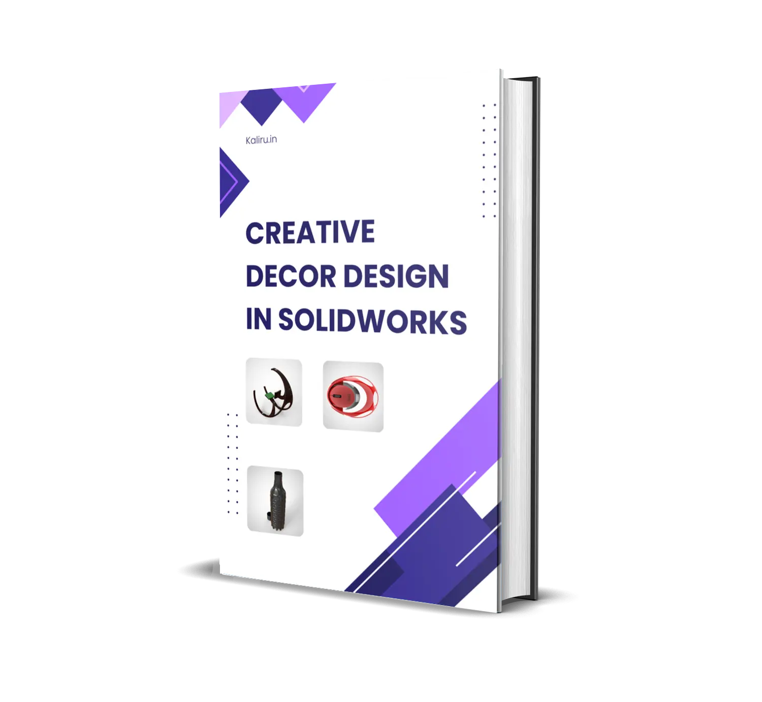
Creative Decor Design in SolidWorks
Rocking wheelchair Design, Patterned waterbottle Design, Egg Shaped mouse
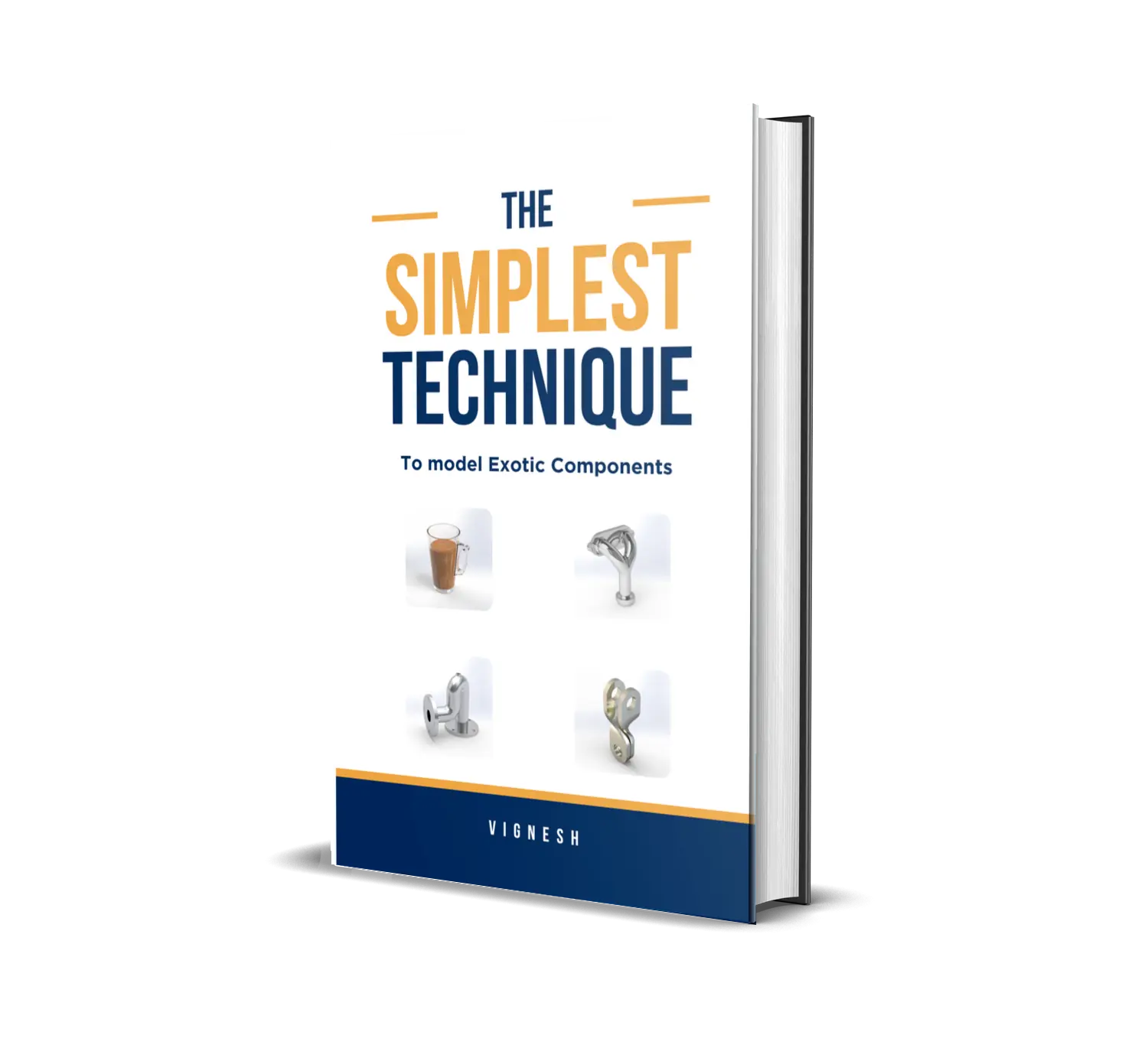
The Simplest Technique to model Exotic Solids
mug , Blow off valve, Flange valve, Turning Tool
Frequently asked questions
Here are some common questions about our company.
solidworks is primarily used in the manufacturing industry to develop product design, component design, and sheet metal because they are the types of modelling that have the greatest practical applications.
Solidworks is used in many different industries, including as engineering, manufacturing, and product design.
Mastering Solidworks will improve job opportunities and also allow you to create products quickly.
Every designer's primary tool is their ability to solve problems. Thanks to its intuitive interface, we can quickly identify and apply the tool's solutions.
Yes absolutely, because
SOLIDWORKS - 3D design tools will continue to be in high demand as the world grows more digitally driven and manufacturing processes get more intricate.
For professionals in a variety of industries, knowing how to utilise SOLIDWORKS, a 3D CAD program that is still extensively used and recognised, is an invaluable ability.
Yes, you can learn with no design experience
It is essentially a user friendly software, which means we can adapt to it more quickly becasue the tools and its options are explained clearly.
You will quickly learn how to use each tool and where to place it after learning how to use it with an example.
If you don't have enough cash to buy our course, you can pay in two installments.