Skip to Content

Automotive Surface Styling


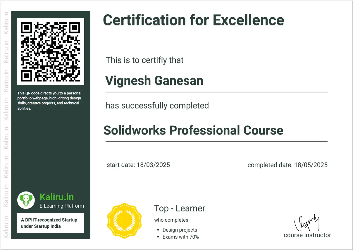
Attend a Free Demo to explore the course, get an overview, and then click 'Learn Now' to enroll.

Learning - 28 Sections - 72 Lectures, 10.5hours On-demand video 

Certifications, Online portfolio development, Hands-on-project

Choose language you prefer to learn, below

For Lifetime acces 

தமிழ் English


For One Year access 

தமிழ்  English

Why should I take this Automotive course 

This comprehensive course is your gateway to transforming your automotive design aspirations into reality. Delve deep into the intricate world of surface modeling in SolidWorks, where you'll acquire the advanced skills necessary to create stunning and realistic car models that capture the essence of automotive elegance. We meticulously guide you through each critical stage of the car design process, starting with fundamental concepts and progressing to advanced techniques. Explore the art of crafting captivating hood and fender curves, meticulously sculpting the subtle contours of doors and windows, and meticulously defining the aerodynamic contours of the rear.

Learning Process


Get Indepth Knowledge from tutorials

Complex Examples


Certification


Hands-on-projects 


Objectives & Assignments

What You will learn

Syllabus


  • Picture Import, Sizing, and Bonnet Surface Area Formation:
    The design process often begins with importing reference images (side, front, and rear views) of the vehicle you're modeling. These images are scaled to the correct dimensions to provide a blueprint for your 3D model. The bonnet (hood) is a crucial starting point. You begin by creating a basic surface representation of the bonnet's general shape, establishing its overall size and curvature. This initial surface acts as a foundation upon which more detailed features will be built.
  • Front End Completion & Fender Surface:
    With the bonnet established, the focus shifts to the front end. This involves refining the bonnet's shape, blending it smoothly into the fender surfaces. The fenders, which house the wheels, require careful sculpting to achieve the desired aesthetic and aerodynamic properties. This stage often involves working with curves and cross-sections to define the complex contours. The fender surface extends from the front of the car, often beginning near the headlights, and flowing back towards the doors.
  • Door Surface Creation:
    The door surfaces are created adjacent to the fenders, maintaining a smooth transition. These surfaces define the side profile of the vehicle and often incorporate subtle curves and creases for styling. The top side of the door often curves to meet the roofline, while the bottom blends into the rocker panel.
  • Relative - Polar Coordinate System:

    During this process, a relative-polar coordinate system is frequently used. This system helps define points and curves in 3D space relative to a central origin, making it easier to control and manipulate the complex shapes of car bodies. It's particularly useful for creating radial or circular features.  
  • Modeling Curvy Front & Bottom Portions:

    Modeling the front of a car, especially the bottom portion, requires careful attention to detail. This area often features complex curves and aerodynamic elements. Start with basic shapes and gradually refine them, using techniques like surface lofting and blending to create smooth transitions between different sections. The bottom portion, often incorporating the lower grille and air intakes, needs to be carefully integrated with the rest of the front fascia.   
  • Headlight & Bottom Fender Surface Creation:

    The headlight housings and the surrounding areas are modeled next. These features are crucial design elements that contribute significantly to the car's identity. The bottom fender surface, which wraps around the lower portion of the wheel well, needs to be carefully blended with the headlight area and the rest of the fender.   
  • Side Door & Quarter Panel Surface Modeling:

    The side doors are further refined, and the quarter panels (the body panels between the doors and the rear wheels) are modeled. These surfaces often incorporate subtle curves and flares to enhance the vehicle's visual appeal. The quarter panel is a significant surface area, often flowing into the rear of the vehicle.   
  • Small Surface Areas at Front and Rear:

    Small, but important, surface areas are then created at the front and rear of the car. These areas might include details around the headlights, taillights, or other design elements. They contribute to the overall cohesiveness of the design.   
  • Bumper Surface Area & Continuity:

    The bumper surfaces are modeled, paying close attention to continuity and smoothness. Bumpers often have complex profiles, especially in modern designs, and require careful shaping to ensure they integrate seamlessly with the rest of the body. The goal is to achieve a smooth, continuous flow of surfaces from the fenders to the bumpers.
  • One-End Bumper Region & Surface Steps:

    Modeling a complex bumper often involves breaking it down into smaller regions. Start with one end of the bumper and gradually work your way across, using small surface steps to define the complex curves and contours. This approach allows for greater control over the shape and ensures a smooth, continuous surface.  
  • Bumper Surface Completion & Quarter Surface Continuation:

    The bumper surface is completed, ensuring a smooth transition between the different sections. The quarter panel surface is then continued, blending it seamlessly into the bumper and the rear of the car. 
  • Quarter Panel Finishing Area & Decklid Beginning:

    The finishing area of the quarter panel is refined, paying attention to details and ensuring a smooth transition to the decklid (trunk lid) surface. The decklid surface is then started, establishing its overall shape and curvature.   
  • Decklid Surface Creation:

    The decklid surface is created, often using 3D curves to define its complex shape. This surface needs to blend smoothly with the quarter panels and the rear window. The drag of the decklid surface (its aerodynamic properties) is also considered during this stage.   
  • Exhaust Surface Modeling & Connection:

    The exhaust surfaces are modeled, starting with the basic shape of the exhaust pipes and then blending them into the rear bumper. The connection of the exhaust surface with the decklid surface needs to be seamless.

    Text Plate Surface Crea​tion:

    Text plates (for logos or model designations) are created using various techniques. These surfaces need to be precisely shaped and positioned to complement the overall design.

    Rear Surface Simulation & Integrity:

    The intricate portion of the rear surface is simulated, ensuring it meets the design requirements and aerodynamic considerations. The integrity of the rear bumper's surface is also checked to ensure it is smooth and continuous.

    Backend Exhaust Surface & Emission Surface Projection:

    The backend exhaust surface is created, along with the projection of the emission surface area (the area where exhaust gases are expelled). This area needs to be integrated seamlessly with the rear bumper.

    Rear Bumper Bottom Point & Surface Door Handle Design:

    The bottom point of the rear bumper surface is defined, and the surface door handle design is created. These details contribute to the overall look and functionality of the vehicle.

    Extraction Vent & Curvy Drift Surface Modeling:

    Extraction vents (for cooling or ventilation) are modeled, and the curvy drift surfaces (areas designed to manage airflow) are sculpted. These features often require complex shapes and careful integration with the rest of the body.

    Bonnet Vent Surface & Completion:

    The vent surface of the bonnet is modeled, and the bonnet surface is completed, ensuring a smooth and continuous shape.

    Aero-Shape & Small Surface Area Closure:

    The overall aero-shape of the vehicle is refined, and any small remaining surface areas on the bonnet are closed.

    Taillight Holding Surface & Completion:

    The surface that holds the taillights is modeled, ensuring a tangential connection with the surrounding surfaces. The taillight surface is then completed.

     Side Surface Bottom Portion & Front Bumper Holding Surface:

    The bottom portion of the side surface is completed, and the surface that holds the front bumper area is modeled.

     Windscreen Structure & Cowl Panel Surface Area:

    The structure of the windscreen (windshield) is initially designed, and the surface area of the cowl panel (the area between the bonnet and the windscreen) is estimated.

     Front End Glass Surface & Roof Surface Modeling:

    The front end glass surface is modeled, and the roof's surface is modeled, sculpting the front-end glass to seamlessly integrate with the roof.

     Side View Mirror Surface & Holding Surface:

    The side view mirror surface is modeled, and a holding surface for the mirror is created.

     Side Door Glass Surface & Rear Light Modeling:

    The side door's glass surface is modeled, and the rear lights are modeled.

     Headlight Modeling & LED Integration:

    The headlights are modeled, incorporating different LED configurations.

     Bumper Grill Holding Surface & Back End Surface:

    The bumper grill's holding surface is modeled, and the back end surface of the grill is modeled.

     Whole Surface Body Building & Completion:

    The entire surface body is built and assembled, ensuring all surfaces are smooth, continuous, and correctly aligned. The complete surface body is then finalized.

     Hub Cap & Tyre Creation:

    The hub caps are modeled, with multiple design options considered. The tires are created using a revolved boss option.

     Disc Brake & Caliper Creation:

    The disc brakes are created using simple steps, and the calipers are modeled using simple tools. These details add realism to the model.


Frequently asked questions

Here are some common questions about our company.

solidworks is primarily used in the manufacturing industry to develop product design, component design, and sheet metal because they are the types of modelling that have the greatest practical applications.

Solidworks is used in many different industries, including as engineering, manufacturing, and product design.

 Mastering Solidworks will improve job opportunities and also allow you to create products quickly.

 Every designer's primary tool is their ability to solve problems. Thanks to its intuitive interface, we can quickly identify and apply the tool's solutions.

Yes absolutely, because

 SOLIDWORKS - 3D design tools will continue to be in high demand as the world grows more digitally driven and manufacturing processes get more intricate.

 For professionals in a variety of industries, knowing how to utilise SOLIDWORKS, a 3D CAD program that is still extensively used and recognised, is an invaluable ability.