
A Complete CAD Mastery Course
Master design with our professional training bundle—SOLIDWORKS for 3D modeling, AutoCAD for precise drafting, and GD&T for standardized tolerances—equipping students and professionals with accuracy, efficiency, and industry-ready skills.
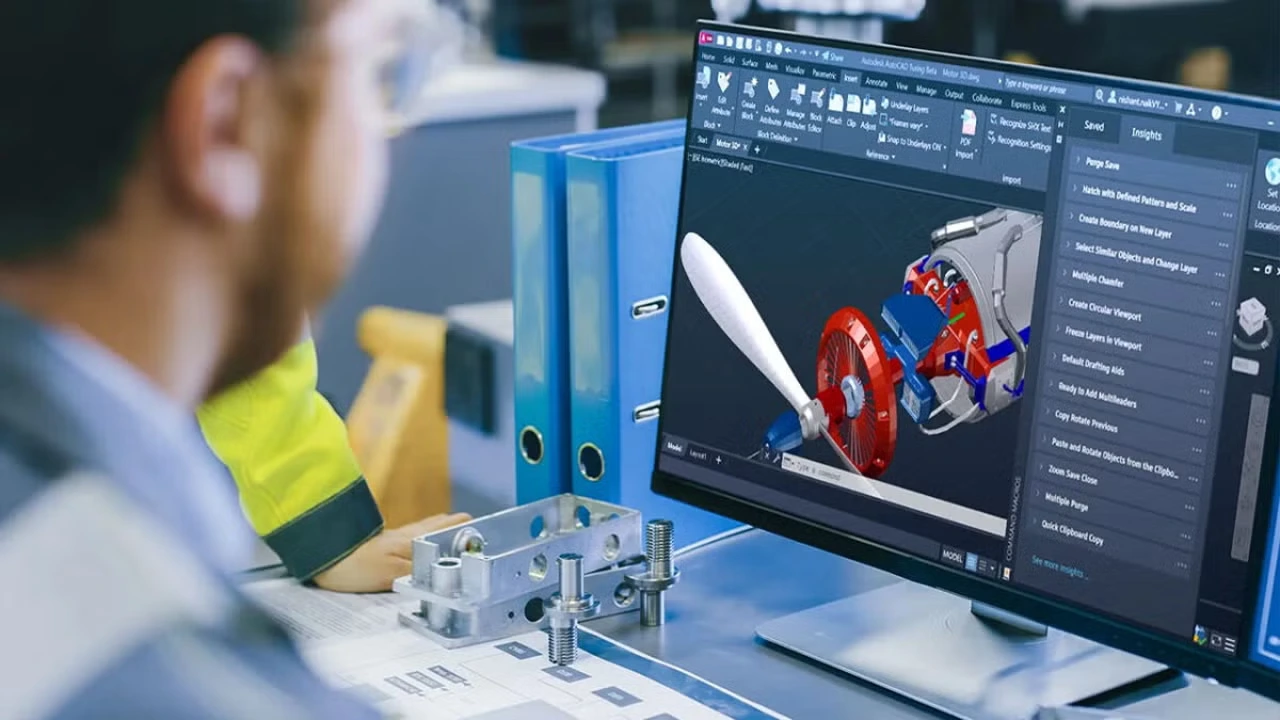
Solid, surface, and sheet metal design are widely used in industries such as automotive, aerospace, consumer products, heavy machinery, and industrial equipment to develop complete product solutions.
Engineers use solid modeling for functional components, surface modeling for aesthetic and ergonomic designs, and sheet metal for lightweight structures and enclosures. Companies like Tata Motors and Airbus apply these integrated skills to design vehicles, aircraft parts, appliances, and industrial systems.

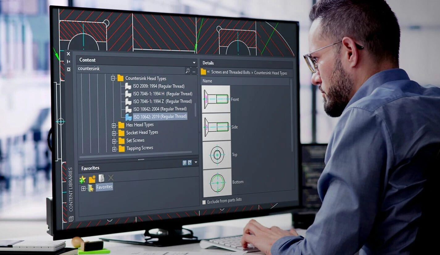
AutoCAD is widely used in industries such as construction, architecture, mechanical engineering, electrical design, interior design, and manufacturing for creating precise 2D drawings and basic 3D models.
Engineers and designers use it for layouts, detailed drafting, shop drawings, plant layouts, and documentation.
Companies like AECOM and Larsen & Toubro rely on AutoCAD for accurate design communication and project execution.
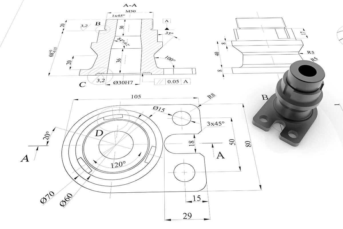
Geometric Dimensioning and Tolerancing (GD&T) is widely used in industries such as automotive, aerospace, defense, medical devices, and precision manufacturing to ensure accurate product functionality, interchangeability, and quality.
Engineers apply GD&T to define form, fit, and function of components like engine parts, assemblies, and critical mechanisms. Companies such as Boeing and General Motors use GD&T to reduce manufacturing variation, improve inspection, and ensure global design standards.
Reverse Engineers capture data using 3D scanning and convert it into accurate CAD models for redesign, repair, and product enhancement. Companies like Bosch and Caterpillar Inc. use reverse engineering to reduce development time, support legacy product maintenance, and enable cost-effective manufacturing.
Jigs & Fixtures Engineers design work-holding devices to position, locate, and guide tools during drilling, milling, welding, and inspection operations. Companies like Toyota and Foxconn rely on jigs and fixtures to improve production efficiency, reduce human errors, and maintain consistent product quality.

The future scope of integrated solid, surface, and sheet metal design is very high due to growth in electric vehicles, smart products, lightweight engineering, and digital manufacturing.
Professionals with multi-domain CAD skills are in demand for roles such as product design engineer, automotive designer, and industrial design specialist.
Emerging technologies like digital twins, generative design, additive manufacturing, and Industry 4.0 are expanding opportunities.

The future scope of AutoCAD remains strong due to continuous demand in infrastructure, smart cities, industrial plants, and digital construction projects. Skilled professionals are required for roles such as CAD drafter, design engineer, and BIM technician.
Companies such as Autodesk and Wipro support digital design transformation, increasing demand for CAD expertise. Integration with BIM, cloud collaboration, and automation tools is expanding career opportunities.
The future scope of GD&T is very high due to increasing demand for precision engineering, automation, and global manufacturing standards. Skilled professionals are required in roles such as design engineer, quality engineer, inspection engineer, and manufacturing engineer.
Companies like Honeywell and Siemens need GD&T experts for advanced manufacturing, aerospace systems, and smart factories. Emerging technologies such as digital inspection, CMM automation, 3D metrology, and Industry 4.0 are increasing demand.
The future scope of reverse engineering is very strong due to growth in digital manufacturing, customization, and product innovation. Industries require skilled professionals for roles such as reverse engineering specialist, design engineer, and product development engineer.
The future scope of jigs and fixtures design is very strong due to increasing demand in automation, robotics, electric vehicles, and smart manufacturing. Skilled professionals are required for roles such as fixture design engineer, manufacturing engineer, and production engineer.
Course Syllabus
It provides an overview of what you are going to learn.
- AutoCAD – FUNDAMENTALS
- Orthographic projection
- Intro about AutoCAD
- How to set units
- How to set Limits
- Function Keys
- Objectives
- CO-ORDINATE SYSTEM
- Absolute coordinate system
- Relative coordinate system
- Relative - polar coordinate system
- Objectives
- SKETCH PROFILES
- Line in profile
- Circle in profile
- Arc in profile
- Ellipse in profile
- Rectangular in profile
- Objectives
- Polygon in profile
- Polyline in profile
- Polyline Edit
- Spline in profile
- Spline Edit
- Objectives
- Point in profile
- Multiline profile
- Multiline Edit
- Region in profile
- SKETCH PROFILES
- Donut in profile
- Objectives
- Example & Practice Drawing
- MODIFYING ENTITIES
- Move Entity
- Copy Entity
- Stretch & Rotate
- Mirror Entity
- Scale Entity
- Objectives
- Trim Entity
- Extend Entity
- Chamfer Entity
- Fillet Entity
- Array – Rectangle
- Array – polar
- Array – Path
- Example & Practice Drawing
- Objectives
- Hatch Entity
- Boundary Entity
- Join Entity
- Explode Entity
- Break & Break at point
- Example & Practice Drawing
- Objectives
- Offset Entity
- Lengthen
- Copy clip & Paste clip
- Zoom Entity
- Subjectives
- DIMENSIONS
- Dimension Tools
- Dimension Radius
- Dimension Associate
- Jogged & Jog line Dimension
- Dimension Edit
- Dimension Style
- Center mark & Center line
- Example & Practice Drawing
- Objectives
- CONSTRAINS & MEASUREMENTS
- Geometrical constrain
- Dimensional Constrain
- Measuring Geometry – Area
- Measuring Geometry
- Objectives
- TEXT & ANNOTAIONS
- Text & Annotations
- Text Style
- Text Edit
- Text Align
- M Text & Annotations
- Objectives
- BLOCK & ANNOTATIONS
- Block Annotation
- Block Edit – point
- Block Edit – Linear
- Block Edit – Polar
- Block Edit – Rotate
- Objectives
- Block Edit – Scale
- Block Edit – Flip
- Block Edit – Array
- Block Edit - BV State
- WBlock Annotation
- Tool Palette
- ATTRIBUTES
- Attribute
- Attribute Multiline
- Enhanced Attribute Edit
- Block Attribute Manager
- Attribute Edit – GATTE
- Attribute Edit – Pedit
- Group
- Example Drawing - Section 01
- Example & Practice Drawing
- Objectives
- LEADER & MULTILEADER
- Q Leader
- MultiLeader
- MultiLeader Style
- MultiLeader Edit
- MultiLeader Collect
- MultiLeader Align
- Objectives
- LAYER & ITS PROPERTIES
- Layer & its properties
- Layer Turn off & Freeze
- Layer Lock
- Layers - Match properties & Match Layer
- Layer plot
- Objectives
- Detail about specific icons in Layers
- Layer - VP Freeze
- Difference of BY Layer & BY Block
- Properties
- Quick properties
- Objectives
- TABLES & LAYOUTS
- Tables annotations
- Layout Setups
- Design center
- Objectives
- MORE FEATURES
- X Line Feature
- Ray Line Feature
- Export Feature
- Image Feature
- Import Feature
- Navigation Bar
- Options Feature
- Purge Feature
- X Ref Feature
- Objectives
- About Isometric
- Example 01 - solid edges
- Example 02 - solid + cylindrical edges
- Example 03 - Sectioned Part
- How to add dimension in isometric
- Things to consider in design
- Product Lifecycle Management
- ntroduction about Solidworks
- Fundamentals of View Tab
- Sketch Profiles
- Modifying Entities
- Sketch Entities – Example
- Extruded Bose feature with Example
- Revolved Bose feature with Example
- Swept Bose Feature with Example
- Plane & its Types
- Lofted Bose feature & its Example
- Boundary Bose
- Hole Wizard & Thread Feature
- Fillet & chamfer
- Pattern feature
- Shell & Draft feature
- Wrap & other modifying feature
- Advance feature
- Example model
- 3D Curves
- Extruded Surface
- Revolved Surface
- Swept surface
- lofted surface
- Boundary surface
- Filled surface
- Planar surface
- offset surface
- Ruled surface
- Delete face
- Replace face
- Knit surface
- Rocking wheel chair
- Egg Shaped Mouse
- Patterned Water Bottle
- Wooden chair
- what is sheetmetal
- Types of cutting machine
- Types of bending machine
- Types of steel sheet
- Sheetmetal from design to maufacturing
- Difference of K-Factor, Bend allowance & Bend deduction
- Practical relation of sheet metal
- Base Flange
- Edge Flange
- Miter Flange
- Brief of Hem
- Brief of Jog
- Sketched Bend
- Cross Break
- Swept Flange
- Corner: Break Corner
- Corner Relief
- Welded corner
- Closed Corner
- Forming tool
- Sheetmetal Gusset
- Extruded cut & simple hole
- Brief of Vent
- Lofted Bend
- Convert to sheet metal option
- About Fold & unfold option
- Flange wall
- T Flex Flange
- Bracket
- Sheetmetal Cabinet Design
- DC power supply Enclosure
- metal Enclosure
- What is Weldment
- Different techniques for creating weldments
- Extraction of weldment external model
- Structural member: Locate profiles
- Trim Extend
- End Cap
- Weldment Gusset
- Weld Bead
- Taffic cone
- Air terminal support
- Table frame
- Top Frame
- Base Holding sturcture
- Angular supporting structure
- Ladder structure
- Top Frame safety structure
- Bottom supporting frames
- Full structure Assembly
- About Assembly
- Assembly in solidworks
- coincident
- parallel
- perpendicular
- concentric
- Fix mate
- Distance
- Tangency
- Angle mate
- Profile center
- Symmetric
- Width
- Linear mate
- Distance limit
- Angular limit
- path mate
- Cam
- Slot
- Gear
- Screw
- Hinge
- Universal joint
- Rack & pinion
- Duplicate parts
- form sub assembly
- Open part
- Isolate
- Exploded view
- Bill of material
- Driven component pattern
- Linear component pattern
- Sketch Driven pattern
- Move & Rotate component
- Standard part
- Smart fastners
- Copy with mate
- Edit component
- Add material
- Top Down assembly
- Interference Detection
- Clearance verification
- Hole alignment
- Assembly visualisation
- Performance
- Mass properties
- Measure
- Section properties
- Body compare
- Curvature
- Costing
- Sustainability
- Import model
- Projected View
- Detail view
- Standard views
- Broken out section
- Break view
- Crop view
- Annotations
- Dimensions
- Note & Pattern
- Balloons
- Layers
- Hatches
- Centerline
- Centermark
- Block
- Hole callout
- Geometric Tolerance
- Datum Feature
- Datum Target
- Surface finish
- Weld Symbol
- General Table
- Hole Table
- Bill of Material
- Bill of Material configure
- Revision
- Weld table
- Weldment cut list
- Bend table
- Punch table
- About GD&T
- What is GD&T?
- Application of GD&T
- Measuring Instrument used in GD&T
- Machines used in GD&T
- Things to know in GD&T
- Objectives & subjective
- Dimensioning
- Dimensioning in GD&T
- Objectives & subjectives
- Tolerance
- What is Tolerance?
- Types of Tolerance
- Difference between Coordinate tolerance & Geometric Tolerance
- Application of tolerance
- Application of Tolerance in Manufacturing
- Objectives & subjectives
- About Datums
- What is Datum?
- How Datum is Applied
- How to Apply Datum in Rectangular part
- How to Apply Datum in Cylindrical part
- Objectives & subjectives
- Positioning of Datum
- External & Internal Datum
- Multiple Datums in one component
- Datum Example
- Objectives & subjectives
- About Datum Target
- What is Datum Target?
- Datum Target in Fix Elements
- Datum Target in Movable Elements
- Datum & Datum Target Requirement
- Objectives & subjectives
- Geometrical Tolerance Symbols
- About Geometrical Tolerance
- Form Tolerance – Flatness
- Form Tolerance – Straightness
- Form Tolerance - Straightness - How to read?
- Form Tolerance – Cylindricity
- Form Tolerance – Circularity
- Form Tolerance - Circularity - How to read?
- Objectives & subjectives
- Orientation – Parallelism
- Orientation - Parallelism - How to read?
- Orientation – Perpendicularity
- Orientation - Perpendicularity - How to read?
- Orientation – Angularity
- Orientation - Angularity - How to read?
- Objectives & Subjectives
- Runout - Total Runout
- Runout - Total Runout - How to read?
- Runout - Circular Runout
- Runout - Circular Runout - How to read?
- Objectives & Subjectives
- Profile - Profile of Line
- Profile - Profile of Line - How to read?
- Profile - Profile of Surface
- Profile - Profile of Surface - How to read?
- Objectives & Subjectives
- Location – Concentricity
- Geometrical Tolerance Symbols
- Location – Symmetry
- Location – Position
- Objectives & Subjectives
- Modifiers
- About Modifier
- Different Symbols in Modifier
- Modifier - Maximum Material Condition with Example
- Modifier - Least Material Condition with Example
- Modifier - Regardless of Feature Size
- Objectives & Subjectives
- Modifier - Tangency Plane
- Modifier – Independency
- Modifier – Translation
- Modifier - Projected Tolerance
- Objectives & Subjectives
- Modifier - Free State
- Modifier - Unequally Disposed
- Modifier - Continous Feature
- Modifier - Conical Taper
- Modifier - Slope Taper
- Objectives & Subjectives
- Feature Control Frame
- About Feature Control Frame
- Subjective
- Virtual & Resultant Condition
- About Virtual Condition
- About Resultant Condition
- Objectives & Subjectives
- About Reverse engineering
- Methods for getting data from an existing model
- Example of How to get info out of an existing model
- Modelling a new product with an imported image
- Using two picture files to model a component
- Converting solid parts from step files
- Unrecognized step file to recognized solid part
- How to get over this and make a new file from an unidentified solid
- Solid part from 3D scanner stl file format
- How to turn a mesh part into a solid part
- How to Extract surface from mesh part
- How to Extract a 3D curve from mesh scaned part
- Procedure for 3D curve extraction from non-mesh part files
- An illustration of surface extraction from a complicated, nonlinear mesh file
- An example of a 3D curve extraction from a complicated mesh file
- Exhaust manifold design
- Alloy wheel Design
- Turbocharger Design
- Piston Design
- Drone arm Design
- Fastner Holder
- Heat Exchanger
- Landing gear
- Asthma Inhaler
- Muscle scraber
- Prosthtic limb
- Syringe Jaw
- Pump Casing
- Shaft coupler
- Turbine blade design
- Valve design
- Pump Impeller
- Turbine Impeller
- Pipe fitting
- Jigs Design consideration
- Fixture Design consideration
- 3-2-1 principle
- Jigs and Fixtures Design details
- About Locating principle
- Types of Locators
- How to Design cylindrical pin - Fits and Tolerance
- Cylindrical Pin material and its Properties
- Cylindrical Pin - Locator size
- Example to Design Pin locators
- Design Pin with Tolerance
- Diamond pin locator
- Conical Locators
- Eccentric Locators
- Nested Locators
- V Locators
- Redundant & Fool Proofing
- About Strap clamps
- Strap clamp Types
- How to Design strap clamp and its types
- Strap clamp Design calculation
- Strap clamp with cam assembly
- Eccentric cam clamp
- Eccentric cam - Edge clamps
- How to Design Latch clamp
- About Toggle clamp & its mechanism
- Verical Handle Toggle Clamp
- Horizontal Handle Toggle Clamp
- Push pull Toggle clamp
- Pnematic Toggle clamp
- Drill Bush and its types
- Liner Bushing
- Press fit Bush
- Head Liner Bushing
- Slip fixed / Renewable bushing
- Template Bushing
- Diamond Groove Bushing
- Head Press Fit Bush
- Serrated Press fit Bush
- Serrated Groove Bush
- About Jigs and its Types
- Plate Jigs Design and Types
- Sandwich Plate Jig
- Table Plate Jigs
- Angle plate Jigs
- Leaf Jig Design
- Indexing Jig Design
- Channel Jig Design
- Box Jig Design
- Template Jig Design
- Front End Completion & Fender Surface
- Exhaust Surface Modeling & Connection
- Text Plate Surface Creation
- Rear Surface Simulation & Integrity
- Backend Exhaust Surface & Emission Surface Projection
- Rear Bumper Bottom Point & Surface Door Handle Design
- Extraction Vent & Curvy Drift Surface Modeling
- Bonnet Vent Surface & Completion
- Aero-Shape & Small Surface Area Closure
- Taillight Holding Surface & Completion
- Side Surface Bottom Portion & Front Bumper Holding Surface
- Windscreen Structure & Cowl Panel Surface Area
- Front End Glass Surface & Roof Surface Modeling
- Side View Mirror Surface & Holding Surface
- Side Door Glass Surface & Rear Light Modeling
- Headlight Modeling & LED Integration
- Bumper Grill Holding Surface & Back End Surface
- Whole Surface Body Building & Completion
- Disc Brake & Caliper Creation
- Material Science and Engineering
- Manufacturing & Production
- Thermodynamics & Heat transfer
- Fluid mechanics
- Mechanical Design General Questions
- Quantitative Aptitude
- Autocad
- Solidworks
- GD&T
Add-on- free course
It provides an overview of what you are going to learn.
- About Global Variable
- How to Apply ?
- Errors in the equation setup
- Properly relate the model to the variable
- Examples for Arithmetic Equation
- Overview about Trignomety
- Sin Equation
- How to apply sin Equation into the model
- Cos Equation
- Tan Equation
- IF Function in Example 01
- IF Function in Example 02
- IF Function in Example 03
- Absolute Function
- Exponential Funtion - Temperature Calculation
- Exponential Funtion -Force calculation
- Integer Function
- Different Units at same model
- Adding Configuration into Equation
- Equation in Surface
- Equation in Solid
- Equations applicable features
- Flip Sketch point
- Example - Flip sketch point
- Patterns
- Example - Patterns
- Move Face
- Defeature - Simplified Geometry
- Defeature - Simplified Geometry Example
- Defeature - silhouette
- Defeature - silhouette Example
- Move & Copy Bodies
- Variable fillet formation
- Pattern for planes
- Pattern for Axis
- Bend Notch formation
- Stamp formation
- Tab & Slot formation
- Multi Flange formation
- Groove Bead in Weldment
- Use of Derived sketch
- Copy with mate in Slot mate
- Copy with mate in Path mate
- Suppress feature
- Surface Finish New Standards
- Bill of material Display state
- Bill of material Configurations
- Bill of material Detailed Cut list in Weldment
- Tolerance in Chamfer
Enrollment Process
choose the access type you prefer to learn
Get a free e-book for lifetime access
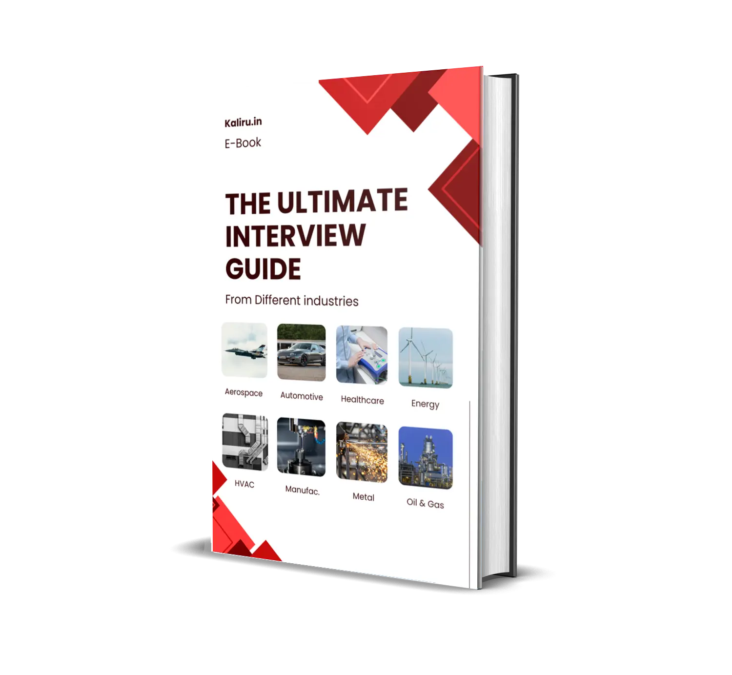
The Ultimate interview guide
Aerospace, Automotive, Healthcare, Energy, HVAC, Manufacturing & Tooling, Metallurgical, Oil, gas & petroleum.

Top Interview Questions & Answers
Material Science and Engineering, Manufacturing & Production,Thermodynamics & Heat transfer, Mechanical Design, Quantitative Aptitude.
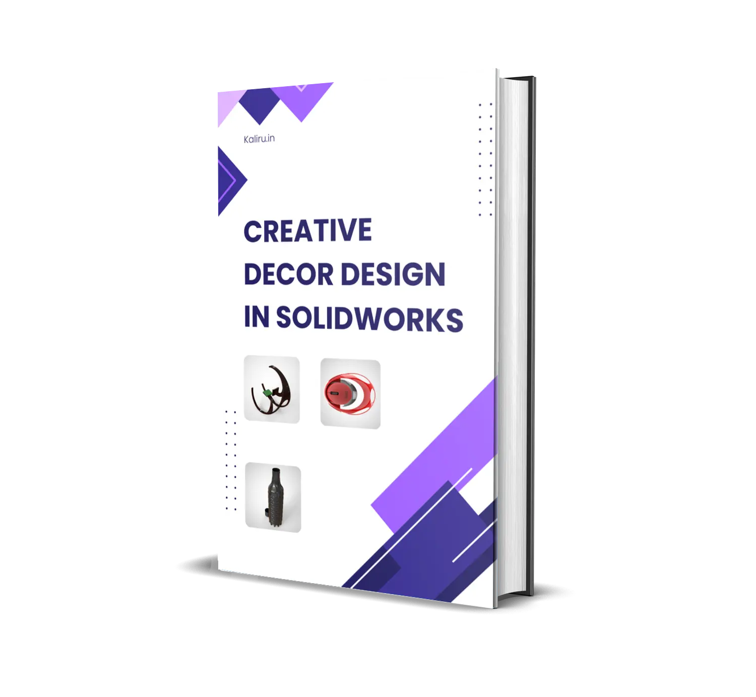
Creative Decor Design in SolidWorks
Rocking wheelchair Design, Patterned waterbottle Design, Egg Shaped mouse
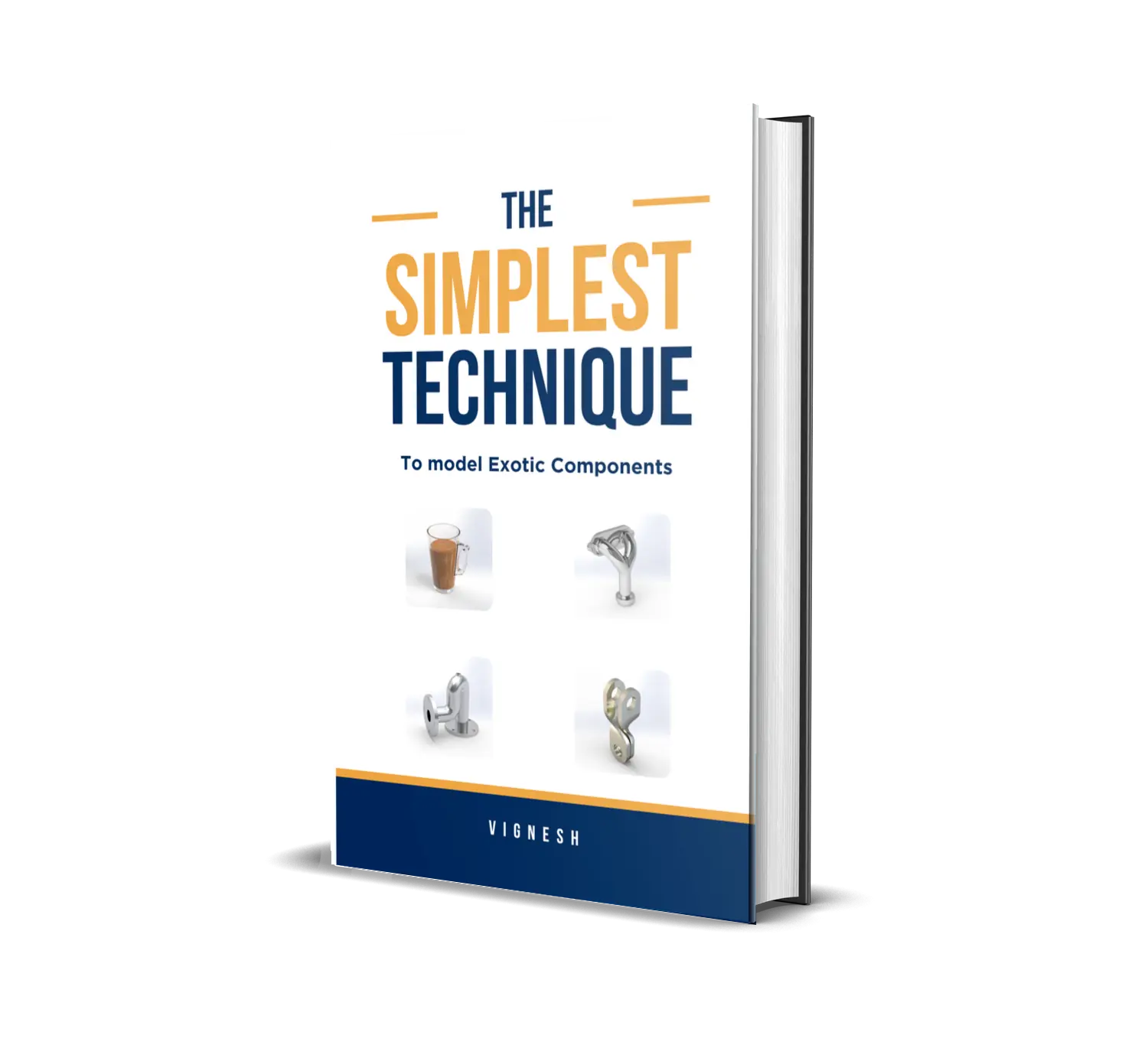
The Simplest Technique to model Exotic Solids
mug , Blow off valve, Flange valve, Turning Tool