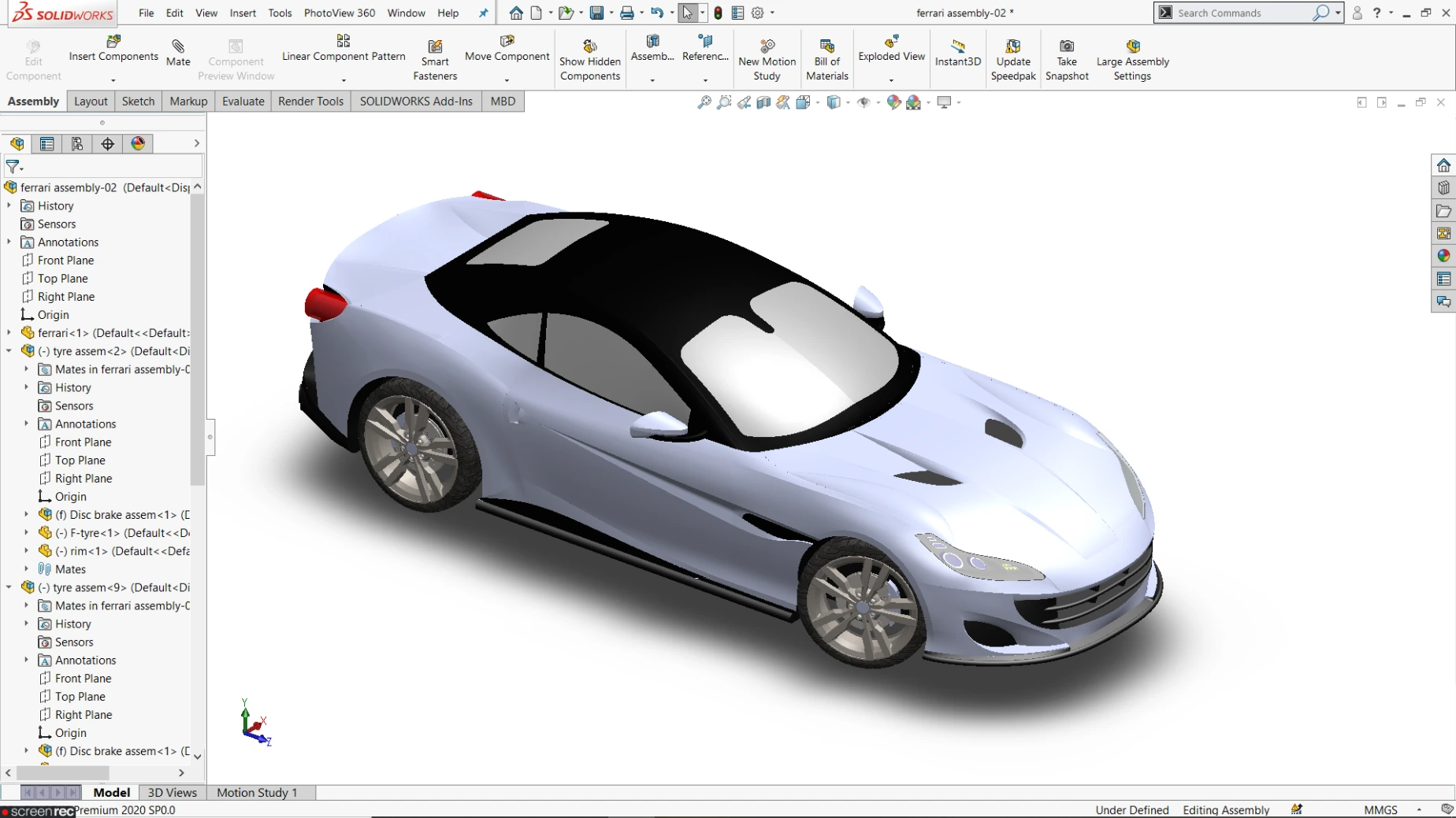
Surface Modeling with Product Design & Automotive styling
This course provides a clear understanding of product design using SOLIDWORKS surface tools, starting with tool fundamentals and progressing to complex examples that demonstrate converting surfaces into solids with defined parameters.
Surface modeling is widely used in industries such as automotive, consumer electronics, aerospace, medical devices, and industrial product design, where aesthetics, ergonomics, and functional appearance are critical.
Designers create complex freeform surfaces for car exteriors, interior trims, dashboards, lighting components, and high-quality consumer products. Companies like Tata Motors and Hyundai Motor Company use advanced surface modeling to develop attractive, aerodynamic, and manufacturable designs.
This course teaches fundamentals and every tool required to build Class-A surfaces, improve product appeal, reduce design iterations, and support prototype development, visualization, and digital validation before production in real industrial environments.
The future scope of surface modeling and automotive styling is very promising due to growing demand for innovative product appearance, electric vehicles, and user-focused design.
Companies such as Tesla, Inc. and Mahindra & Mahindra require skilled surface designers to develop modern and sustainable vehicle designs.
Opportunities include automotive surface designer, product stylist, digital sculptor, and transportation designer. Emerging technologies like VR-based design review, digital twins, AI-driven styling, and rapid prototyping are increasing industry demand.
This course provides strong fundamentals and tool-based expertise, enabling professionals to work in global design studios, innovation centers, and startups, ensuring long-term career growth and global opportunities.

Course Syllabus
It provides an overview of what you are going to learn.
- PLM and Stage Types
- How to develop a Product with Example
- What are the stages in Business cycle
- 3D Curves - Composite & Project cuves
- Helix & spiral curve
- Helix & spiral curve - section 02
- Helix & spiral curve - section 03
- Helix & spiral curve - section 04
- Curves through XYZ point
- Curves through reference point
- Split line
- Split line - other types
- Extruded Surface
- Extruded Surface – Draft
- Revolved surface
- Objectives
- Swept surface
- Swept surface with guide curves
- Lofted surface
- Objectives
- Boundary surface
- Boundary surface in aerofoil shape
- Filled surface
- Planar surface
- Objectives
- Offset surface
- Ruled surface
- Ruled surface - Taper & perpendicular to vector
- Ruled surface – Sweep
- Delete face – Delete
- Delete face - Delete & patch
- Delete face - Delete & fill
- Objectives
- Replace face
- Delete hole
- Extend face
- Trim surface
- Trim surface types
- untrim surface
- untrim surface detail
- Objectives
- Knit surface
- Thicken
- Cut with surface
- 3D Curves - Composite & Project cuves
- Objectives & Practice Drawings
- Rocking wheel chair - How to create a body
- Rocking wheel chair - How to create Leg
- Rocking wheel chair - How to use trim
- Rocking wheel chair - How to create Backrest
- Rocking wheel chair - final body
- Patterned Water Bottle
- Wooden chair - from sketch to surface
- Wooden chair - For surface to solid
- Egg shaped mouse
- World cup Model
- Front End Completion & Fender Surface
- Exhaust Surface Modeling & Connection
- Text Plate Surface Creation
- Rear Surface Simulation & Integrity
- Backend Exhaust Surface & Emission Surface Projection
- Rear Bumper Bottom Point & Surface Door Handle Design
- Extraction Vent & Curvy Drift Surface Modeling
- Bonnet Vent Surface & Completion
- Aero-Shape & Small Surface Area Closure
- Taillight Holding Surface & Completion
- Side Surface Bottom Portion & Front Bumper Holding Surface
- Windscreen Structure & Cowl Panel Surface Area
- Front End Glass Surface & Roof Surface Modeling
- Side View Mirror Surface & Holding Surface
- Side Door Glass Surface & Rear Light Modeling
- Headlight Modeling & LED Integration
- Bumper Grill Holding Surface & Back End Surface
- Whole Surface Body Building & Completion
- Disc Brake & Caliper Creation
Enrollment Process
choose the access type you prefer to learn
Get a free e-book for lifetime access

The Ultimate interview guide
Aerospace, Automotive, Healthcare, Energy, HVAC, Manufacturing & Tooling, Metallurgical, Oil, gas & petroleum.
Creative Decor Design in SolidWorks
Rocking wheelchair Design, Patterned waterbottle Design, Egg Shaped mouse